


Logistics equipment such as plastic returnable containers and corrugated cardboard boxes is highly susceptible to damage during the logistics process.
The primary cause of this damage is the impact from drops during transportation and distribution, which causes severe plastic deformation or even material failure in the equipment.
Currently, research on returnable containers and corrugated cardboard boxes primarily relies on physical testing, but this method is highly destructive to the containers, and repeated testing drives up costs.
Computer simulation technology continues to advance. Simulation methods can model diverse complex working conditions with higher accuracy.
These techniques supply reliable data for scientific research. They also exert an increasingly prominent role in promoting the development of the packaging industry.
Ansys/LS-DYNA is a well-known general explicit nonlinear dynamic analysis software. It can simulate many types of complex nonlinear behaviors.
These include material nonlinearity, geometric nonlinearity, and contact nonlinearity.
It is particularly well-suited for solving nonlinear dynamic impact problems such as high-speed collisions, explosions, and metal forming.
Ansys/LS-DYNA has limited capabilities for preprocessing tasks such as model data and mesh generation.
Gaps, overlaps, and misalignments in the model can cause significant difficulties in finite element modeling.
These issues involve the suppression of small features and the meshing of complex geometries;
Poor preprocessing can compromise mesh quality and, in severe cases, result in the finite element model becoming unsolvable, distorted results, or even insurmountable obstacles.
HyperMesh is a highly efficient finite element preprocessing software that enables convenient and flexible cleaning and optimization of finite element models.
By using its mesh generation tools to rapidly create finite element meshes, it significantly improves the efficiency of finite element preprocessing.
A method involving preprocessing with HyperMesh, followed by solving the problem in Ansys/LS-DYNA, and finally postprocessing the results in LS Prepost, has become an efficient and reliable approach for drop analysis.
We adopt the three aforementioned software tools in this paper and carry out drop simulation analysis for the newly designed transport container.
We extract plastic strain, stress and other relevant parameters from the simulation results.
These parameters help us conduct a more comprehensive and reasonable evaluation of the transport container.
Structural Design of Transport Containers
Currently available corrugated cardboard boxes and plastic transport containers both have significant drawbacks.
The manufacturing process for corrugated cardboard boxes is highly polluting, with low recycling and recovery rates.
Their mechanical properties—including compression resistance, drop resistance, and resistance to impact and vibration—are inadequate.
These boxes perform poorly in special environments such as humid conditions. Transporting most goods often requires internal cushioning materials.
These cushioning materials improve the shock absorption effect.
Although plastic returnable containers have better mechanical properties than corrugated cardboard boxes, their cushioning performance is poor, and even localized damage can render the entire container unusable.
This paper designs a modular plastic returnable container. The new design solves the defects of the above logistics equipment.
It cuts the output of transportation packaging waste. The design reduces resource consumption. It also lowers environmental pollution.
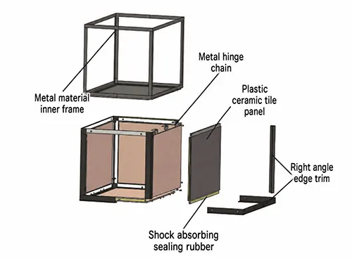
The structure of the pallet is shown in Figure 1.
A metal inner frame serves as the skeleton; the inner edges of the plastic corrugated panels on the four sides and the bottom each come into contact with the inner frame.
Right-angle edging forms the outermost structural layer. The four upper edges of the four side panels adopt a different structure.
Designers combine metal strips and plastic corrugated panels to form these edges instead of using right-angle edging.
We install cushioning rubber sealing strips between the right-angle edging and the outer edges of plastic corrugated panels.
The right-angle edging, cushioning rubber seal, and plastic corrugated panels are secured to the inner frame using hexagonal socket round-head screws and rivet nuts;
Workers assemble hexagon socket round-head screws and rivet nuts. They coat low-strength adhesive on the fasteners.
The adhesive stops threads from loosening when impact compresses the cushioning rubber seal.
A metal hinge links one side of the lid’s plastic corrugated sheet to the inner frame.
We fit plastic frames and metal trim to the remaining three sides of the lid.
The top frame of the inner frame forms the edging for the four side edges that make contact with the lid.
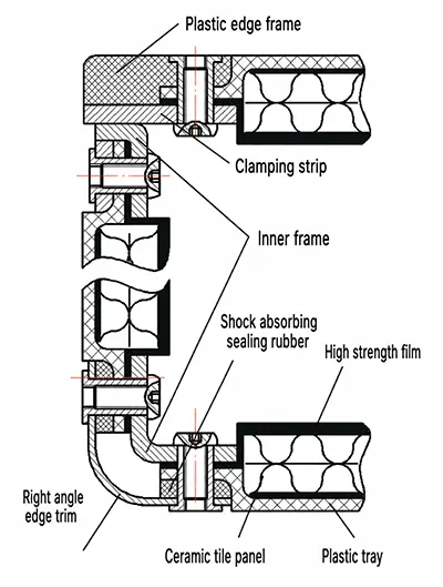
The structure of the plastic corrugated board is shown in Figure 2.
It is bonded together from an inner high-strength film, a middle corrugated cardboard layer, and an outer plastic shallow tray.
The intermediate cushioning layer can consist of solid foam, rubber, expanded plastic, or nonwoven cushioning materials;
It can also be made from recycled corrugated cardboard (see Figure 2), which improves the utilization rate of corrugated cardboard and reduces environmental pollution and waste of resources.
Crate Drop Analysis
HyperMesh-Based Crate Meshing
During transportation and handling, vibration and impact are the primary causes of product damage.
Among various impact scenarios, drop impact is the most direct factor leading to damage to packaging and poses a significant threat to it.
Physical testing is time-consuming and costly, and can no longer keep pace with the pace of development; therefore, drop simulation is particularly essential for physical design.
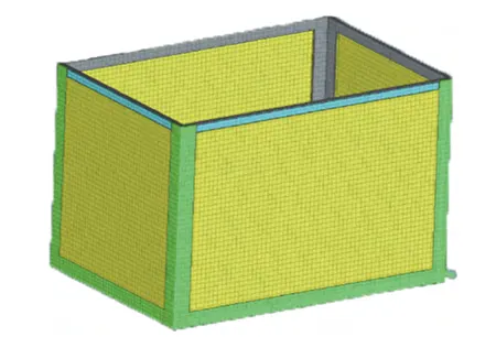
The external dimensions of the box model are 640 mm × 440 mm × 450 mm (similar to those of standard shipping containers).
The model is an assembly consisting of numerous parts with features such as fillets and circular holes.
Ansys software fails to meet the meshing requirements, so we adopt HyperMesh to carry out preprocessing on the model, as shown in Figure 3.
Parameter Definitions
See Table 1 for the specific parameters of the selected materials.
| Material | Density (g·cm⁻³) | Young’s Modulus (MPa) | Poisson’s Ratio | Yield Strength (MPa) | Shear Modulus (MPa) |
|---|---|---|---|---|---|
| Q235 Steel | 7.85 | 207,000 | 0.30 | 235 | 6,100 |
| 6061 Aluminum | 2.90 | 69,000 | 0.33 | 156 | 3,000 |
| PP Plastic | 0.92 | 896 | 0.42 | 100 | 89 |
| Silicone Rubber | 1.02 | 230 | 0.40 | 1.38 | 3.5 |
Table 1. Material Parameters
In this study, we assign metallic material properties to both the flange and the inner frame.
Metallic materials are isotropic, and the bilinear model adapts to small-strain problems of isotropic materials, so we select the bilinear model.
This model adopts the Mises yield criterion. It uses two linear segments to describe the stress-strain characteristics of materials.
Researchers determine the stress-strain curve by four key parameters.
These parameters include elastic modulus, Poisson’s ratio, yield stress and shear modulus.
The model is an assembly consisting of solid components, so we select Solid elements.
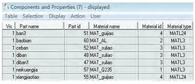
After that, we assign corresponding elements and materials to different parts in the model, as shown in Figure 4.
In this figure, Part IDs 47, 48, and 52 represent the bottom plate and side plates of the drive housing;
Part IDs 51 and 55 represent the rubber gaskets; and Part IDs 60 and 57 represent the outer flange and inner frame, respectively.
Key Terms for the Solution
1. Definition of Initial Velocity and Solution Time
This simulation models a scenario in which a worker accidentally drops a box from a height of 0.8 to 1.2 m.
GB/T 4857.18—1992 defines matching drop heights for transport packaging units of different masses under various transportation modes.
We choose a 1 m drop height to better reflect actual working conditions.
Calculation time correlates closely with multiple factors such as model complexity and drop height.
Computers spend more time finishing calculations when models become more complex or drop heights increase.
We aim to guarantee accurate results, lower CPU occupancy and shorten computation time.
We equate free fall from 1 m with zero initial velocity (gravitational acceleration 9.8 m/s²) to another working condition.
This equivalent setting uses an initial velocity of 4.4145 m/s at the instant the box contacts the ground, with a drop height of 0 for simulation analysis.
That is, only the time interval after contact with the ground during the drop is calculated, and the simulation duration is set to 0.2 s.
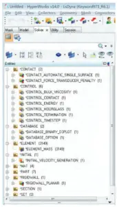
Add the keyword INITIAL_VELOCITY_GENERATION, and set the parameter VZ to 4414.5 (initial velocity set to 4414.5 mm/s);
Set the CONTROL_TERMINATION parameter to 0.1, which represents the simulation duration;
Set DATABASE_BINARY_D3PLOT DBplot to 0.004 (50 frames played over 0.2 s).
2. Definition of Contact and Force Sensors
LS-DYNA offers three contact surface handling algorithms: Single Surface contact, Node-to-Surface contact, and Surface-to-Surface contact.
LS-DYNA also provides nine assembly types: Standard, Automatic, Rigid Body, Fixed, Fixed Failure, Erosion, Edge, Draw Bead, and Forming.
The model mainly involves contact between the surfaces of two objects without mutual penetration, so we select Node-to-Surface contact.
The fastening form is a screw-and-nut connection; we set the assembly type as Rigidly Coupled and select CONTACT_AUTOMATIC_SINGLE_SURFACE on the tab, and then define a force transducer.
Here, CONTACT_FORCE_TRANSDUCER_PENALTY is selected.
3. Definition of Rigid Walls and Setting the Drop Angle
In LS_DYNA, select RIGIDWALL_PL-ANAR for the rigid wall, and use nodes to define a rigid wall surface.
Different drop angles can be achieved by rotating the model. In this paper, the drop simulations were analyzed using a 15° angle and a vertical drop (where the drop angle is defined as the angle between the bottom surface of the box and the ground).
4. Mass Settings
Given that recreating interior components in the model is not only complex but also highly susceptible to affecting simulation results if set up improperly, a new layer of nodes was created on the floor inside the operating chamber.
The mass of each node was set so that the total mass was 60 kg, thereby simulating the loaded conditions inside the chamber.
This approach not only facilitates the simulation but also ensures more accurate results.
5. Definitions of All Keywords
See Figure 5 for specific keyword definitions.
Analysis of Solution Results Based on LS-PREPOST
1. 15° Angled Drop
The outer bottom edge is the area where deformation is most pronounced;
It plays a crucial protective role for the entire container during a drop, so we will conduct a detailed analysis and discussion of this edge here.
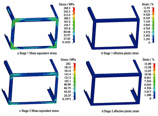
The results of the 15° angled drop simulation analysis are shown in Figure 6.
Stage 1 corresponds to the instant when the bottom flange collides with the ground.
As shown in Figure 6a, the forces acting on the outer flange during this stage are highly uneven.
Most of the frame experiences relatively low forces, with equivalent stress not exceeding 54 MPa.
However, near the two bottom corners of the impact edge, the equivalent stress exceeds 54 MPa, reaching a maximum of 269 MPa in localized areas.
The local equivalent stress near the bottom corners exceeded the yield strength of 6061 aluminum alloy, resulting in plastic deformation.
However, as shown in Figure 6b, the maximum effective plastic strain at this point was 11.9%, which did not exceed the elongation at break of 6061 aluminum alloy (16%);
Therefore, the material did not fail due to fracture.
After Stage 1, the effective plastic strain near the bottom corner continued to increase, while the equivalent stress at various locations gradually decreased until Stage 2.
Stage 2 represents the completion of the impact; at this point, the strain no longer changed.
As shown in Figure 6d, the maximum effective plastic strain was 15%, occurring near the tip of the bottom corner within an extremely small area, and did not exceed the elongation at break of 6061 aluminum alloy (16%).
Furthermore, as shown in Figure 6c, the maximum equivalent stress at the outer edge was 200 MPa, occurring near the tip of the bottom corner.
Only a very small number of locations near the bottom corner exhibited equivalent stresses exceeding 156 MPa (the yield strength of 6061 aluminum alloy), while equivalent stresses in most other parts of the frame did not exceed 40 MPa.
2. Vertical Drop
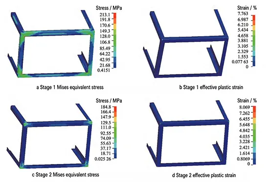
The results of the vertical drop analysis are shown in Figure 7.
Stage 1 corresponds to the moment when the bottom flange collides with the base surface.
Figure 7a shows the stress state at this instant. Loads concentrate mainly near the four bottom corners of the flange.
Equivalent stress exceeds 156 MPa only within tiny local regions of the bottom corners.
156 MPa is the yield strength of 6061 aluminum alloy. This phenomenon triggers plastic deformation.
Furthermore, as shown in Figure 7b, the effective plastic strain at this location is only 7.76%, far below the elongation at break of 6061 aluminum alloy.
Thereafter, the equivalent stress gradually decreases while the effective plastic strain gradually increases, until Stage 2—when the collision is complete—at which point the effective plastic strain ultimately stabilizes at 8.7%.
Conclusion
Engineers commonly use HyperMesh to simulate complex assemblies, including auto parts and whole vehicles.
We apply this software to packaging drop testing. This provides a new technical route for designing and simulating new-generation logistics equipment.
We complete preprocessing in HyperMesh and perform calculations using LS-DYNA.
The drop simulation finds that the four bottom corners are the vulnerable positions of the designed turnover box under two working conditions.
Side panels only sustain slight damage.
This provided important guidance for further structural improvements and significantly reduced design time.
At the same time, the simulation validated that the modular returnable containers—designed with lightweight and compact dimensions in mind—exhibit good drop resistance.
Furthermore, since the edge trim can be removed and replaced after damage, this significantly extends the service life of the containers.
To a certain extent, they can replace current corrugated cardboard boxes and plastic returnable containers, offering promising application prospects.