


Currently, amid the global wave of the Green Revolution—and particularly as environmental protection requirements in international trade become increasingly stringent— many countries have imposed restrictions on export packaging materials.
Environmental Challenges in Packaging Materials
Packaging cushioning materials such as polyethylene foam (EPE) and expandable polystyrene (EPS) cause irreversible harm to the natural environment due to issues like difficulty in recycling and slow degradation.
Therefore, finding alternatives to non-biodegradable packaging materials is a matter of urgent priority.
Polypropylene (PP) honeycomb sheets are plastic sheets with a honeycomb structure produced through extrusion molding using PP as the primary raw material.
They are lightweight, high-strength, and recyclable.
As an eco-friendly material, they are widely used in the packaging industry as a primary substitute for corrugated cardboard, wood, and metal sheets.
However, compared to corrugated paper packaging materials, PP hollow panels have drawbacks such as higher costs and lower cushioning performance, and have thus far been unable to fully replace corrugated paper packaging materials in packaging applications.
High-Calcium-Filled PP Hollow Panels
Calcium carbonate (CaCO₃) is currently the most widely used filler in polyolefin polymer materials, offering a high cost-effectiveness ratio;
Adding an appropriate amount of CaCO₃ can effectively enhance the rigidity of PP materials while reducing production costs. Currently, most PP sheets on the market use conventional filler ratios, with a CaCO₃ mass fraction typically around 30%.
Although this ratio improves performance and reduces costs to some extent, the resin matrix remains the primary component, leaving room for further optimization of material costs.
High-calcium-filled PP hollow panels, with a CaCO₃ filling ratio increased to over 50%, minimize the use of higher-priced PP resin, achieving an optimal balance between stiffness, cost, and overall performance.
PP hollow panels primarily provide support through deformation of the core layer; their cushioning performance is generally inferior to that of corrugated paper materials.
However, as an engineering material capable of plastic deformation, PP hollow panels can withstand repeated and complex mechanical loads.
Furthermore, hollow panel components formed through interlocking exhibit load-bearing performance that is significantly superior to that of corrugated paper components.
Research Gaps and Engineering Challenges
Current research literature on PP structural panels largely focuses on honeycomb panels; in contrast, there is relatively little attention paid to PP hollow panels, and research on high-filler calcium carbonate PP hollow panels and their engineering components is virtually nonexistent.
With the continuous development of hollow panels and the ever-expanding scope of their applications, existing research is no longer sufficient to address structural issues encountered in practical applications.
Research Objectives and Practical Significance
To address these issues, this paper takes a high-calcium PP hollow panel as the research subject and selects common basis weights (800, 900, and 1,000 g/m²) and structural configurations (cross-shaped, grid-shaped, and triangular) to investigate the mechanical properties and load-bearing performance of high-calcium PP hollow panels and their structural components.
Tensile tests were conducted to analyze the anisotropic mechanical properties of high-calcium-filled hollow panels;
We conducted tear strength tests and vertical compression tests to analyze the failure modes and load‑bearing performance of components during collapse.
Based on these findings, researchers designed three interlocking structures, namely cross-shaped, triangular, and grid-shaped structures, to systematically explore the influences of rib orientation and basis weight on compressive performance.
The research findings not only provide a clear path for cost reduction in PP hollow boards but also offer a reference for the design of PP hollow board components.
They hold significant practical value for promoting the widespread adoption of lightweight, low-cost sheet materials in fields such as packaging and logistics.
Experimental Section
Main Raw Materials
PP: EP300H, Jinneng Chemical (Qingdao) Co., Ltd.;
CaCO₃: Particle size 5 µm, Zhejiang Changxing Zhonghong New Materials Co., Ltd.;
Titaniumate coupling agent: NDZ-201, Dongguan Kangjin New Materials Technology Co., Ltd.;
Color masterbatch: LY-815, Suzhou Linyuan Plastics Technology Co., Ltd.;
Antioxidants 1010 and 168: Industrial grade, Dongguan Dinghai Plastics & Chemicals Co., Ltd.;
Polyethylene wax: W501, Dongguan Kangjin New Materials Technology Co., Ltd.
Major Instruments and Equipment
Twin-screw extruder: SHJ-35, Nanjing Guangda Rubber & Plastic Machinery Factory;
Roller-type haul-off machine: DY-2, Zhangjiagang Leyu Yongbang Machinery Factory;
Electronic Universal Testing Machine: CMT4304, Meters Industrial Systems (China) Co., Ltd.;
Compressive Strength Tester: PN-CT300B, Hangzhou Pinxiang Technology Co., Ltd.;
Scanning Electron Microscope (SEM): ZEISS Sigma 300, ZEISS GmbH, Germany.
Material Preparation
The preparation of PP hollow panels consists of four stages.
(1) Raw material Pretreatment.
First, CaCO₃ powder is added to a high-speed mixer preheated to 115 °C and premixed for 3 minutes at a speed of 250 r/min to remove moisture.
Next, the titanate coupling agent NDZ-201 (1% by mass of CaCO₃) is slowly added to the mixer over the course of 1 minute.
Afterward, researchers raise the main shaft speed to 750 r/min and activate the flying knife rotating at 2,000 r/min.
Mixing continues at 115 °C for 10 minutes until the material reaches a uniform, dry, free-flowing, and loose powder state.
Next, researchers blend the raw materials according to the following mass percentages: PP (46%), modified CaCO₃ (50.7%), color masterbatch (2%), polyethylene wax (1%), and antioxidants (a mixture of 1010 and 168, totaling 0.3%).
(2) Melt Extrusion and Molding.
Researchers transport the premix to a co-rotating parallel twin-screw extruder using a vacuum feeder. The extruder features seven independent temperature control zones spanning from the feed inlet to the die head.
The temperature control zones of the extruder, from the feed inlet to the die, are set up with a gradual temperature increase: Zone 1 (feed inlet) is 170 °C;
Zones 2, 3, and 4 (melting sections) are 185, 190, and 195 °C, respectively; Zones 5 and 6 are both 200 °C; and Zone 7 is 200 °C.
Temperature control is achieved through the equipment’s built-in multi-channel PID (Proportional-Integral-Derivative) intelligent temperature control system, ensuring that the processing temperature remains stable within the set range throughout the entire process.
(3) Cooling, Shaping, and Drawing.
The high-temperature sheet extruded immediately enters a three-roll calender and a cooling water tank for rapid cooling and shaping, after which it is drawn out at a constant speed by a draw-off unit to ensure the sheet’s flatness and dimensional stability.
(4) Post-processing.
After the continuous sheet is cut to length or wound into a roll, it undergoes inspection for surface quality, thickness, and basis weight.
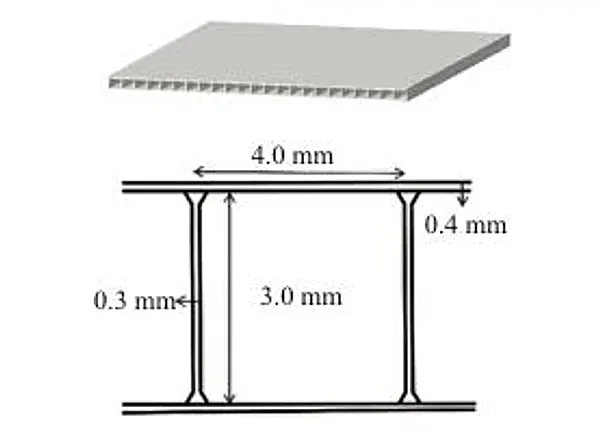
The manufactured sheet is shown in Figure 1, with a nominal thickness of 3.8 mm, a rib width of 0.3 mm, top and bottom sheet thicknesses of 0.4 mm, and a core layer height of 3 mm.
Performance Testing
Researchers performed tensile, tear strength, and vertical compression tests on high-calcium PP sheets to support the subsequent static compression analysis of structural components.
Researchers performed all tests at a temperature of (23±2) °C and a relative humidity of 50%±10%.
1. Tensile Test
Researchers performed tensile tests on three groups of specimens with basis weights of 800, 900, and 1,000 g/m² in both longitudinal and transverse directions.
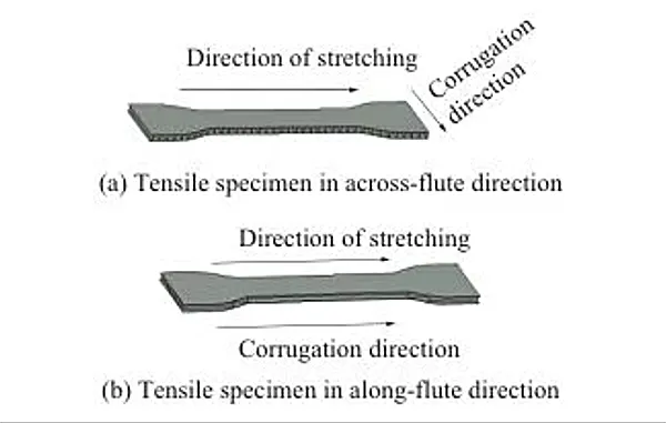
Figure 2 shows a schematic diagram of a tensile test specimen.
As illustrated, researchers define the transverse direction as the loading direction perpendicular to the corrugation orientation and the longitudinal direction as the loading direction parallel to the corrugation orientation.
Researchers accordingly define the terms “transverse to the flutes” and “perpendicular to the flutes” used in the following text.
The dumbbell-shaped tensile test specimens measured 35 mm × 160 mm, with a gauge length of 70 mm.
A universal testing machine was used for the tests, with a test speed of (50 ± 5) mm/min.
Each group consisted of no fewer than five specimens to ensure sufficient valid results and thereby obtain the relevant tensile property parameters.
2. Tear Test
To evaluate the tear resistance of high-calcium PP sheets, researchers adopted the right-angle tear test in accordance with the standard QB/T 1130-1991, Test Method for Right-Angle Tear Resistance of Plastics.
Researchers performed right‑angle tear tests on specimens with basis weights of 800, 900, and 1 000 g/m².
Researchers applied tensile load to standard specimens to trigger tearing at the right-angle notch and recorded the corresponding tear load.
Each test group consisted of no fewer than 5 specimens, each measuring 100 mm × 34 mm, with a test speed of 200 mm/min.
3. Vertical Compression Test
In accordance with GB/T 1041-2008, researchers performed vertical compression tests on panels with cross-rib and longitudinal-rib structures at basis weights of 800, 900, and 1,000 g/m².
Researchers recorded the maximum vertical compression force. All test specimens were sized at 100 mm × 60 mm, and each group contained no fewer than five replicates.
4. Static Compression Test
When designing the structure of PP hollow panels, the corrugation direction and structure are key factors affecting their load-bearing performance.
The uniformly distributed corrugations inside the hollow panel can enhance its compressive strength in both vertical and non-vertical directions, prevent deformation and failure, and provide better impact resistance and shock absorption.
Since hollow panels are resistant to bending and possess high resilience, efforts should be made to minimize bonding during structural research to avoid interfering with test results.
Therefore, researchers fabricated the test specimens in this study with a slot structure consistent with that of the hollow panel cutting jig.
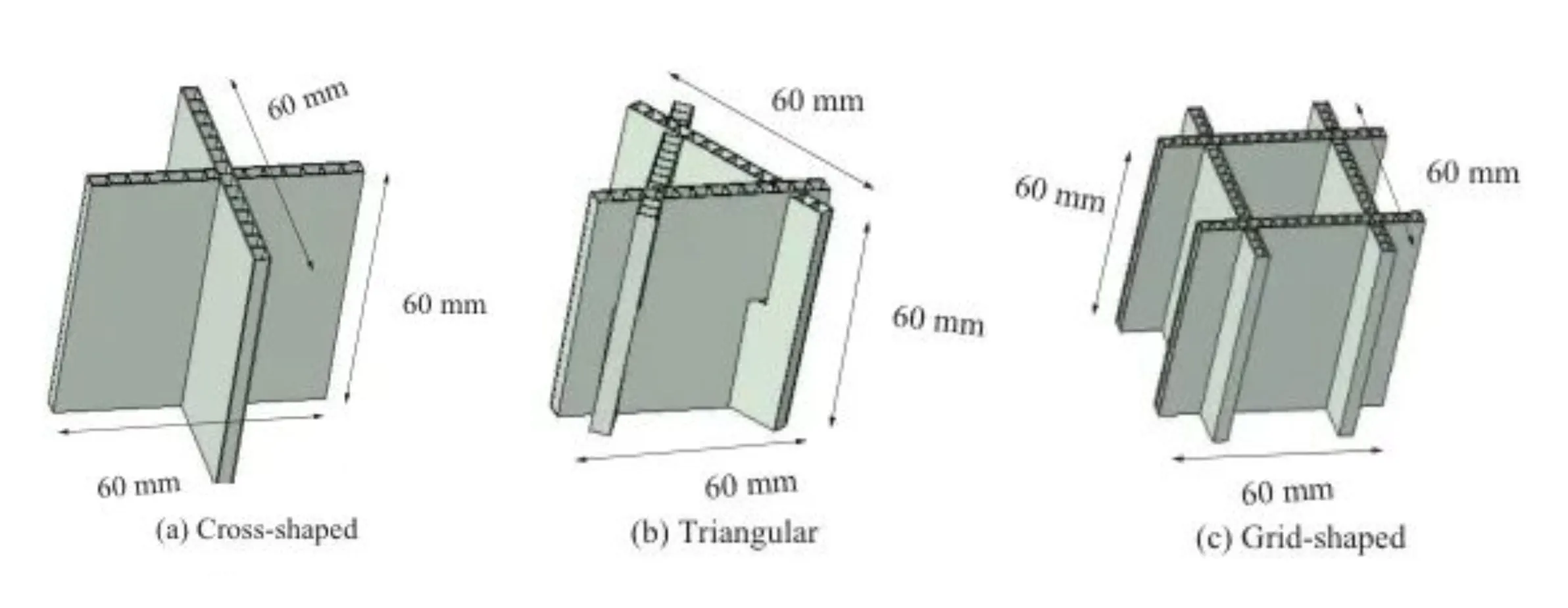
Researchers selected three typical structures, namely cross-shaped, triangular, and grid-shaped structures, to explore the effects of structural factors on compressive performance.
> Specimen Preparation and Structural Configurations
The specific experimental protocol is as follows.Prepare three sets of panels with basis weights of 800, 900, and 1,000 g/m².
Use a sample-cutting machine to cut them into 60-mm-sided squares, ensuring that each panel has at least 15 reinforcing ribs.
Figure 3 shows schematic diagrams of vertical rib compression test specimens with different structures.
Researchers cut 4-mm-deep notches according to structural characteristics to achieve diverse forming effects.
Specifically, they made cross-shaped notches at the exact center of the panels and triangular and grid-shaped notches 10 mm away from the panel edges.
Researchers performed static compression tests on the specimens with a universal testing machine.
Researchers centered the specimen on the test platform and lowered the upper platen at a constant rate of 12 mm/min until full compaction of the specimen was achieved.
To minimize experimental error, researchers selected seven identically specified specimens for compression testing, eliminated outliers, and averaged the data from five valid specimens.
After completing the tests, researchers acquired load-displacement data and curves and plotted the corresponding average curve.
Researchers evaluated the load-bearing capacity based on the ultimate load, which refers to the maximum load a structure can sustain before initial failure or instability appears on the load-displacement curve.
Results and Discussion
Tensile Testing
Researchers excluded specimens with test data deviating from the group mean by more than two standard deviations and retained data from five valid specimens.
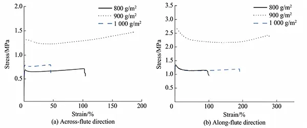
They calculated the final average performance values based on the valid data. Figure 4 presents the stress–strain curves obtained from the tensile tests.
Researchers analyzed the test data to determine the mechanical property parameters of the material, as summarized in Table 1.
As shown in Table 1, the tensile modulus of elasticity in the vertical rib direction is significantly higher than that in the transverse rib direction (81% higher on average).
The tensile modulus of elasticity in the vertical rib direction exhibits a significant nonlinear increase with rising basis weight;
It increased by 23.8% when the basis weight rose from 800 g/m² to 900 g/m², while the increase dropped sharply to 3.1% when the basis weight increased from 900 g/m² to 1,000 g/m², indicating that the filler-reinforcement effect tends to saturate after 900 g/m².
In contrast, the tensile elastic modulus in the transverse direction exhibits an accelerating growth trend.
Based on the comprehensive tabular test data, the tensile properties of samples with different basis weights in both fluting directions follow this order: 900 g/m² panels > 1,000 g/m² panels > 800 g/m² panels.
| Basis weight (g/m²) | Flute direction | Tensile modulus (MPa) | Anisotropy coefficient | Breaking force (N) | Yield stress (MPa) |
|---|---|---|---|---|---|
| 800 | Across | 207.44 | 1.77 | 107.41 | 1.41 |
| 800 | Along | 117.18 | 1.77 | 58.16 | 0.73 |
| 900 | Across | 256.86 | 1.96 | 219.32 | 2.60 |
| 900 | Along | 130.90 | 1.96 | 121.03 | 1.41 |
| 1,000 | Across | 264.72 | 1.70 | 149.08 | 1.74 |
| 1,000 | Along | 155.56 | 1.70 | 61.14 | 0.78 |
Tab. 1 Tensile performance parameters of hollow board
Tear Strength Test
During the tear strength test, researchers observed that the specimens fractured at the right‑angle notch after approximately 3 s, exhibiting distinct and rapid crack propagation.
After processing the test data, they eliminated outliers and retained five valid specimens, then computed the average value as the final test result.
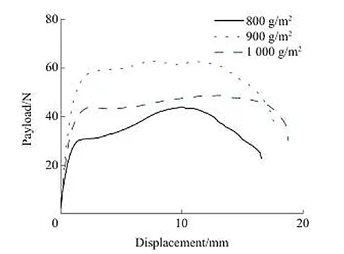
Figure 5 shows the load-displacement curves for the tear strength tests of three groups of hollow panels with different grammages.
As shown in Figure 5, the 900 g/m² panel exhibited the best tear resistance, followed by the 1,000 g/m² and 800 g/m² panels.
Researchers ranked the tear resistance of samples with different basis weights as follows: 900 g/m² panel > 1 000 g/m² panel > 800 g/m² panel.
Microscopic Fracture Mechanisms
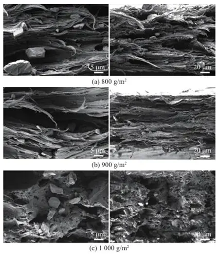
Figure 6 shows micrographs of the samples after tearing.
The fracture surfaces in Figures 6a and 6b both exhibit characteristics of ductile fracture, as evidenced by the presence of numerous “filamentous” structures and “pebble-like” filler particles (CaCO₃).
The “filamentous structures” are ductile fibers formed when the PP matrix undergoes extensive plastic deformation during tearing, causing the molecular chains to stretch and orient until fracture occurs.
In Figure 6c, the 1000 g/m² sample presents obvious honeycomb-like voids and filler particles on its fracture surface.
This phenomenon demonstrates that the dominant fracture mechanism transitions from toughness failure to interfacial failure.
Researchers confirmed that honeycomb-like voids form after calcium carbonate fillers detach from the PP matrix interface.
Particle pull-out and interfacial delamination collectively generate these characteristic cavities.
This indicates that under high basis weight conditions, the uniformity of filler dispersion decreases, causing the filler-matrix interfacial bond strength to become the weak link.
Under load, stress concentrates at the interface, leading to rapid delamination, the formation of voids, and their interconnection.
Consequently, the material fractures before sufficient plastic deformation occurs, resulting in a decline in its tear resistance.
Vertical Compression Test
Researchers processed the test data to eliminate outliers and retained five valid specimens.
They calculated the final results by averaging the corresponding test data and obtained the vertical compression forces for the two flute orientations, as summarized in Table 2.
Analysis by flute orientation revealed a significant difference between the transverse and longitudinal flute orientations, with a nearly fivefold difference in experimental values.
The difference in load-bearing capacity among different basis weights was even more pronounced in the vertical corrugation direction; panels with a basis weight of 900 g/m² exhibited vertical compression performance that was, on average, 45% higher than those with basis weights of 800 g/m² and 1,000 g/m².
In the vertical corrugation direction, the load is borne by densely spaced ribs, which undergo stable compressive failure, resulting in a high vertical compression force.
When the corrugation runs horizontally, the load is borne by the large surface area of the thin sheet, causing elastic buckling of the sheet, resulting in an extremely low vertical compression force.
However, the three sets of samples for both corrugation orientations exhibited the same trend in vertical compression force: 900 g/m² panels > 1,000 g/m² panels > 800 g/m² panels.
Effect of Flute Direction and Basis Weight
In summary, researchers preliminarily conclude that corrugation direction exerts a significant effect on the load‑bearing performance of the members, and the panels achieve optimal load‑bearing performance at a basis weight of 900 g/m².
| Basis Weight (g/m²) | Along-Flute Direction (N) | Across-Flute Direction (N) |
|---|---|---|
| 800 | 341.82 | 88.18 |
| 900 | 545.94 | 100.80 |
| 1,000 | 423.74 | 93.44 |
Tab. 2 Vertical compression test results for boards in three basis weight groups.
Based on the above test results, the following conclusions can be drawn:
There are significant differences in mechanical properties depending on the corrugation direction, with the vertical direction showing significantly higher performance than the horizontal direction.
Among the different basis weights, the 900 g/m² panels exhibited the best mechanical properties, followed by the 1,000 g/m² and 800 g/m² panels.
The differences in mechanical properties across basis weights were even more pronounced when the fluting orientation was vertical.
The panels exhibited poor tear resistance; structural members may experience tearing at joints during static compression.
Analysis of Structural Member Load-Bearing Performance
1. Static Compression Tests on Cross-Shaped Members with Different Rib Orientations
Researchers performed static compression tests on cross-shaped structural members with a basis weight of 800 g/m².
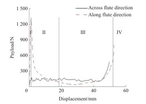
Figure 7 shows the load-displacement curves for different rib orientations; the peak value of the load-displacement curve for the vertical rib orientation is significantly higher than that for the horizontal rib orientation, which is in good agreement with the test results for the mechanical properties of the panels.
The load-bearing capacity of the two orientations differs by nearly a factor of 8, indicating that the load-bearing capacity of the vertical-flute structure is far greater than that of the horizontal-flute structure.
> Compression Behavior in the Vertical Rib Direction
Researchers divide the load-displacement curve under longitudinal rib loading into four stages: linear elastic stage, yield stage, plateau stage, and consolidation stage.
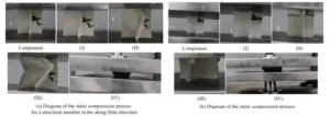
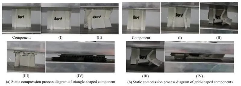
Figure 8 illustrates the compression process of the member in the vertical and transverse directions.
Linear Elastic and Yield Stages
During the linear elastic stage (Stage I), the curve rises linearly. Researchers note that this stage lasts a relatively short period: the load‑bearing capacity increases rapidly to its peak, and the structure transmits stress in a linear manner.
Because it is a thin-walled hollow structure, the plate rapidly loses stability under stress and undergoes local elastic buckling.
The compression state of the member when it reaches the ultimate load is shown in Figure 8a(I).
The member along the compression direction exhibits slight wave-like creases near the slots, while the member perpendicular to the compression direction bends slightly to the right.
During the yield stage, the load curve shows a rapid decline, and the deformation of the member becomes increasingly pronounced as plastic deformation begins to occur.
As shown in Figure 8a(II), the member continues to deform along the indentations and at the points of bending.
Plateau and Energy Absorption
During the plateau stage, the displacement of the vertical-rib structure continues to increase, but the load value remains within a stable range, exhibiting a plateau phenomenon.
At this point, the structure absorbs energy, and the member bends inward or to the right around the creases, being compressed to half its original height with severe deformation;
However, the plateau stage presents an extremely low load level.
Researchers confirm that crack initiation and propagation undermine structural integrity and cause instantaneous deterioration of load-bearing capacity.
The structure absorbs negligible energy throughout this process while maintaining a persistently low load level.
During the densification stage, researchers observe complete crushing of the cross-shaped structure.
The unit cells squeeze into close contact and aggregate tightly, while the structural material undergoes severe compressive deformation.
At this point, the member’s stiffness becomes extremely high, and the load surges sharply.
> Compression Behavior in the Transverse Rib Direction
Transverse-ribbed members have a transverse structure; the sequential collapse of the ribs causes the load-displacement curve to fluctuate up and down at the ultimate load.
In the early stage of the curve, there are only two phases—linear elasticity and yield—resulting in a sawtooth-shaped fluctuation curve that repeats continuously as displacement increases.
The plateau stage is characterized by a sustained sawtooth-shaped fluctuation curve, with stable fluctuations in force and deformation;
The member undergoes layered compression and eventually enters the densification stage.
Guided by the progressive bending deformation in the transverse rib direction, a stable plastic collapse and progressive buckling mode is exhibited until the structure is compressed to the densification stage, at which point the load rises linearly as the deformation increases.
Local Fracture and Collapse Mechanisms
Due to the unique sandwich configuration of hollow panels, researchers find that loading perpendicular to the core hollow direction triggers rapid, discontinuous local fractures and buckling failures.
This deformation behavior leads to a sharp drop in compressive bearing capacity, producing a typical accordion-like collapse mode.
Analysis shows that the load-displacement curves of structural members in the vertical rib direction exhibit four stages, among which the linearly elastic and yield stages are very brief, with the majority of the behavior concentrated in the plateau stage.
The plateau stage features a long, flat curve, indicating poor energy dissipation by the members, which is consistent with the conclusions from the tear force tests.
However, neither set of members experienced tearing at the interlocking joints during deformation, indicating that the structural characteristics cause forces during compression to concentrate on the members in all directions rather than at the joints.
Since the two sets of test specimens were highly consistent, the displacements at the densification stage were nearly identical.
Comparison of Rib Orientations
The tests also demonstrated that the vertical rib direction exhibited stable plastic buckling and folding, exhibiting strong resistance to initial impact; in contrast, the transverse rib direction experienced unstable fracture and brittle failure.
As packaging components, they are inherently fragile, have low energy-absorption efficiency, and exhibit unstable and unpredictable behavior during the process.
2. Static Compression Tests on Specimens with Different Basis Weights and Structures
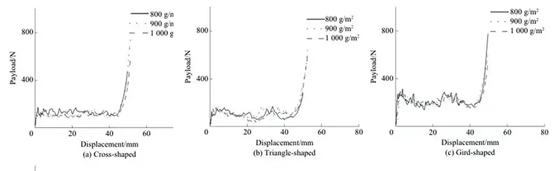
Figure 9 shows the load-displacement curves for specimens with different grammages and structures tested in the transverse direction.
The peak values and trends of the curves for the three structures show no significant differences, indicating that, for all three structures, grammage has a relatively minor effect on load-bearing performance when tested in the transverse direction.
The load-displacement curve for the cross-shaped member remains relatively stable, while the triangular and grid-shaped members exhibit an increase in load as compression approaches the joints.
> Longitudinal Load-Bearing Performance
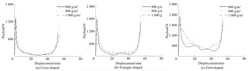
Figure 10 shows the load-displacement curves for specimens with different basis weights and vertical-rib structures.
A comprehensive analysis of the graphs for the three structures reveals that the 900 g/m² specimens exhibit the highest ultimate load;
This is particularly evident in the grid-pattern structure, consistent with the higher yield stress observed for the 900 g/m² specimens in the tensile test.
When testing the mechanical properties of the material, the 1,000 g/m² sample performed better than the 800 g/m² sample;
But the results of the compression tests on structural members show the opposite trend.
This indicates that at 1,000 g/m², excessive stiffness causes global buckling, with a low buckling critical load, whereas at 800 g/m², lower stiffness makes the material prone to local buckling, resulting in a moderate ultimate load that is, however, lower than that of the 900 g/m² material.
Analyze the effect of unit weight on different structural members.
For cross-shaped and triangular structures, unit weight affects the ultimate load but has little effect on the platform load.
Researchers observe a prolonged low-load plateau phase.
This characteristic behavior primarily stems from geometric instability, which governs structural failure instead of material yield strength.
For the cross-shaped structure, the load affects both the ultimate load and the plateau load, and the plateau phase exhibits “significant fluctuations and large variations.”
The performance of the cross-shaped structure is jointly dominated by “material strength/stiffness” and “stable local buckling.”
> Basis Weight and Structural Design Implications
Based on the above analysis, it can be seen that changes in basis weight do not significantly alter the performance of members in the transverse direction.
However, in the longitudinal direction, changes in basis weight result in significant changes in the ultimate load of all three structural members, all following the order: 900 g/m² panels > 800 g/m² panels > 1,000 g/m² panels.
The 900 g/m² members exhibit the optimal mechanical performance, consistent with the previous material mechanical property test results.
However, the 800 g/m² and 1000 g/m² structural members exhibit a contrary performance trend compared with the results obtained from previous material tests.
Researchers attribute this discrepancy to different failure mechanisms: material strength governs the failure of sheet specimens, while structural stability dominates the mechanical response of assembled structural members.
Excessive stiffness (1,000 g/m²) can actually trigger unstable global buckling, resulting in performance that is even worse than that of more flexible members (800 g/m²).
This finding further demonstrates that engineers cannot directly predict the structural performance of hollow-panel structures based solely on material mechanical properties during practical design.
The plateau periods for the cross-shaped and triangular structures remained unchanged, while the plateau period for the grid-shaped structure showed significant variation: the plateau period was most unstable at a basis weight of 1,000 g/m², followed by 900 g/m² and 800 g/m².
This is because the high stiffness of the 1,000 g/m² panels leads to the accumulation of high elastic strain energy, triggering sudden and unstable failures, such as multiple buckling or microcracking.
Accordingly, engineers can adopt panels with lower basis weights for transverse rib orientation to reduce overall costs.
For vertical rib orientation, the 900 g/m² panel serves as the optimal structural option.
3. Static Compression Tests on Specimens with Different Structures in Different Flute Orientations
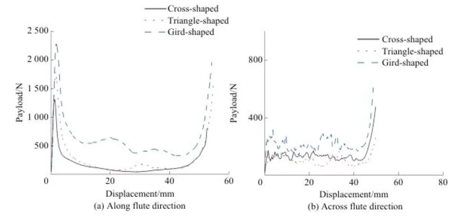
Taking an 800 g/m² hollow board as an example, this study investigates the static cushioning performance of three structural configurations—cross-shaped, triangular, and grid-shaped—as shown in Figure 11.
> Ultimate Load and Compression Behavior
Figure 11 presents the ultimate load of different structures under vertical flute orientation.
Researchers rank the ultimate bearing capacity in descending order as grid-shaped, triangular, and cross-shaped structures.
The ultimate load increases linearly across the three structural configurations.
The curve profiles of the three structures are similar, all undergoing a linearly elastic stage, a yield stage, a plateau stage, and a densification stage.
The first two stages are brief and rapid, while the stability of the plateau stage is ranked as follows: cross-shaped, triangular, and grid-shaped.
Owing to its distinctive structural characteristics, the checkerboard configuration forms supportive components on the compression plane via members perpendicular to the loading direction when compressed to half its initial height.
This process establishes a new load-bearing unit, as illustrated in Figure 12b(III).
Consequently, the curve exhibits an alternating rise and fall during the plateau phase.
The triangular structure is inherently stable; however, because its mesh density is lower than that of the grid pattern and its element area is smaller, the plateau load is lower, and its load-bearing performance is inferior to that of the grid pattern.
Researchers observe a single fluctuation in the plateau stage.
This phenomenon occurs because structural compression up to half the initial height generates a new supporting surface, as illustrated in Figure 12a(III).
> Transverse Load-Bearing Performance
In terms of transverse load-bearing capacity, the limit loads of the three structural configurations, from highest to lowest, are: grid, cross, and triangle.
All three load-bearing curves exhibit a sawtooth pattern, with the grid configuration showing more pronounced fluctuations.
Researchers identify three major peaks across the full curve. The first two peaks appear shortly after test commencement.
When compression reduces the member to half its initial height, the load rises markedly.
This observation reveals that the joints improve the load‑bearing capacity of grid‑shaped members.
The triangular member did not perform as well overall as the other two structures, but, like the grid-shaped member, it exhibited a sudden increase in load when compressed to half its original height.
> Comparison of Structural Performance
Based on the above analysis, it can be seen that the grid-shaped member exhibits the best mechanical performance.
Whether loaded vertically or horizontally, the dense grid structure delivers uniform and rigid support and effectively restrains local buckling.
The triangular member performs better than the cross-shaped member when loaded in the vertical rib direction but performs worse than the cross-shaped member when loaded in the horizontal rib direction.
This may be because, in the vertical rib direction, the base of the downward-pointing triangle is parallel to the loaded plate, forming a stable “arch-shaped” or “A-shaped” support system that effectively transfers the load to the boundary, resulting in strong buckling resistance.
In the transverse rib direction, the contribution of the triangular hypotenuse to preventing panel buckling decreases, making the panel more prone to buckling in relatively long unsupported regions, thereby weakening the advantages of the triangular structure.
Therefore, triangular structures exhibit different results in the two rib directions.
4. Summary of Component Load-Bearing Performance
Based on an analysis of different components in terms of fluting orientation, basis weight, and structure, the following conclusions can be drawn from the results of static compression tests.
(1) Fluting Orientation and Load-Bearing Performance
There are significant differences in load-bearing performance among components with different fluting orientations;
Vertical fluting orientation shows significantly higher performance than horizontal fluting orientation, consistent with the results of mechanical property tests on the panels.
(2) 900 g/m² Delivers Optimal Structural Performance
For different structural configurations, the load-bearing performance was consistent across basis weights: the 900 g/m² panel exhibited the best mechanical performance, followed by the 800 g/m² and 1,000 g/m² panels.
This differs from the results of the panel mechanical property tests; the reason is that the dominant mechanisms governing mechanical behavior differ between panels and structures, leading to variations in the results.
In sheets, mechanical behavior is primarily determined by the material’s stiffness and flexibility; material performance does not increase monotonically with rising basis weight.
The 800 g/m² specimen exhibited the poorest performance due to the lowest absolute material content.
The anomalous performance of the 1,000 g/m² specimen was attributed to excessively high filler content, which caused interfacial defects and matrix embrittlement.
In contrast, the 900 g/m² basis weight achieved the best synergy between the filler and the PP matrix, maintaining good toughness while ensuring high stiffness, thereby yielding the optimal overall mechanical properties.
For structural members, structural stability and failure modes became the dominant factors affecting performance.
The 1,000 g/m² component, due to its excessive stiffness and significant brittleness, experienced unstable global buckling or brittle fracture at the joints, resulting in the poorest energy absorption capacity.
Although the 800 g/m² component had lower strength, its good toughness enabled stable crushing, yielding better performance than the 1,000 g/m² component.
The 900 g/m² member, however, possesses the optimal balance of stiffness and ductility, achieving stable and high-load progressive buckling and demonstrating the best overall performance.
(3) Grammage Effects Depend on Rib Orientation
The differences in ultimate load capacity among members of different grammages are more pronounced when the ribs are oriented vertically;
For members with ribs oriented horizontally, an increase in grammage has a relatively minor effect on the load-bearing performance of the three structures.
(4) Structural Design Prevents Joint Tearing
Although the panels have poor tear resistance, no tearing occurred at the joints during static compression of the members.
This indicates that the structural characteristics cause forces to concentrate on the members in all directions rather than at the joints during the compression process.
(5) Grid Structure Delivers 51% Higher Load Capacity
Among the different structures, the grid-shaped structure exhibited the best load-bearing performance, averaging 51% higher than that of the cross-shaped and triangular structures.
Conclusions
(1) Corrugated Panel Mechanical Properties
Mechanical property tests revealed significant differences between the two flute orientations, with vertical flutes providing substantially better mechanical properties than horizontal flutes.
During the tear strength test, the panels tore rapidly within a short period, suggesting that compression may cause fractures at the joints.
Overall, the 900 g/m² panels demonstrated the best mechanical properties, followed by the 1,000 g/m² and 800 g/m² panels. The material’s stiffness and flexibility primarily determine its mechanical properties.
(2) Flute Orientation Affects Load Capacity
The peak value of the load-displacement curve for the vertical flute orientation was significantly higher than that for the horizontal flute orientation, with a nearly eightfold difference in load-bearing capacity between the two.
Horizontal-flute components exhibit extremely low load-bearing capacity, poor energy absorption, and unpredictable brittle failure during compression.
Therefore, packaging designers should avoid placing the flutes perpendicular to the primary load direction whenever possible.
Instead, designers should prioritize a vertical-flute orientation, with the flute direction aligned with the applied load.
This configuration provides the packaging with more stable and efficient load-bearing and cushioning performance.
(3) Optimal Basis Weight for Load Performance
For vertical-flute specimens, changes in basis weight significantly affect performance;
However, for unstable horizontal-flute specimens, increasing the basis weight does not effectively improve their load-bearing capacity.
In the vertical-flute orientation, 900 g/m² components exhibit the optimal balance between load-bearing capacity and energy absorption, outperforming those with basis weights of 800 g/m² and 1,000 g/m².
Excessively high basis weight may lead to instability. Due to excessive stiffness, 1,000 g/m² members are prone to accumulating excessive elastic strain energy under compression (especially in grid-like structures), triggering sudden brittle failure or multiple buckling, which leads to instability during the plateau phase.
When members must bear loads in the transverse rib direction, engineers can select low-basis-weight panels to reduce costs while ensuring basic performance.
When members bear loads in the transverse direction, engineers should prioritize 900 g/m² panels to achieve optimal structural performance.
(4) Grid Structure Offers Superior Stability
Member stability primarily determines the load-bearing performance of different structures.
Among the three structures, a comparison of stability during the plateau phase shows that the cross-shaped structure > the triangular structure > the grid-shaped structure.
However, the grid-shaped structure offers the optimal and most reliable overall mechanical performance.
Its core advantage is its ability to provide stable and consistently strong support regardless of whether loads act in the transverse or longitudinal direction.
Therefore, when load-bearing performance is a consideration in packaging structure design, the grid-shaped structure should be the preferred solution.
The conclusions of this study are based on standard 60 mm × 60 mm test specimens and clarify the load-bearing capacity and failure mechanisms of different structures.
However, the study has limitations; actual large-scale components may exhibit scale effects due to different boundary conditions.
Future research should incorporate testing and simulation in accordance with product standards to verify the performance patterns from test specimens to actual products and advance engineering applications.