


Polycarbonate panels have become increasingly common in roofing systems for stadiums, railway stations, airports, and other major public buildings. Several major projects have adopted solid or hollow polycarbonate panels as roofing materials.
These projects include Beijing Workers’ Stadium, Shenzhen Universiade Sports Center, the Belarus National Football Stadium, and Xiong’an Railway Station. Their applications demonstrate the growing importance of polycarbonate roofing systems.
Polycarbonate hollow panels offer low weight, high light transmission, thermal insulation, impact resistance, and convenient installation. Manufacturers produce rectangular, X-shaped, and V-shaped multilayer cavities, along with flat and curved panel configurations.
Common products contain two to seven layers and range from 4 to 30 mm in thickness. Their structural configurations vary according to span requirements and intended applications.
Polycarbonate U-shaped locking hollow panels, hereafter called U-shaped hollow panels, use mechanical connections at their supporting locations. These connections simplify construction and improve waterproofing performance.
Their multilayer cavities also provide enhanced vertical stiffness and thermal insulation. Consequently, engineers increasingly select these panels for practical construction projects.
Existing industry standards permit finite element calculations that consider geometric nonlinearity when evaluating polycarbonate panel deflection. However, they provide no explicit calculation procedure for U-shaped hollow panels.
They also lack dedicated formulas, vertical displacement limits, and sufficient experimental verification. Designers therefore commonly select panel specifications using completed project experience, span dimensions, and manufacturer test reports.
Such empirical methods lack comprehensive theoretical and standardized support. Unusual snow or wind loads can make previous project experience unreliable for structural safety assessments.
This study investigates two U-shaped hollow panels with different locking configurations, designated Panel A and Panel B. It combines small-displacement thin-plate theory, experimental testing, and nonlinear finite element analysis.
The research develops a theoretical formula for calculating maximum vertical displacement. Its findings provide a reference for engineering applications involving similar hollow panel systems.
Small-Displacement Theoretical Calculation
Theoretical Calculation of Solid Thin-Plate Displacement
Polycarbonate is a polymer material with relatively uniform and stable properties. Classical thin-plate displacement theory therefore provides a theoretical foundation for analyzing U-shaped hollow panels.
The conventional thin-plate displacement equation assumes small deformation and considers bending stress while neglecting in-plane membrane stress. Equation (1) expresses the maximum vertical displacement under uniformly distributed loading.
Here, μ represents the deflection coefficient, q denotes uniformly distributed loading, and a represents the characteristic panel width. Additionally, D denotes bending stiffness, E represents elastic modulus, and ν represents Poisson’s ratio.
The conventional theory primarily applies when ω is smaller than the panel thickness t. Under this condition, bending deformation dominates the panel response.
When ω exceeds t, Equation (1) produces increasingly significant errors. As the ω/t ratio increases, theoretical displacement values can become unacceptably large.
Consequently, the conventional equation loses practical engineering significance under large-displacement conditions. A modified calculation approach must therefore account for geometric nonlinear effects.
Equivalent Thickness Calculation for Multilayer Hollow Panels
U-shaped hollow panels contain multiple internal cavities, so their actual thickness cannot directly represent an equivalent solid plate. The small-displacement condition must instead use equivalent thickness teq.
Likewise, Equation (2) must substitute teq for the original plate thickness. This substitution allows the model to represent the bending stiffness of multilayer panels.
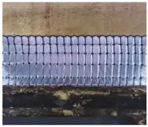
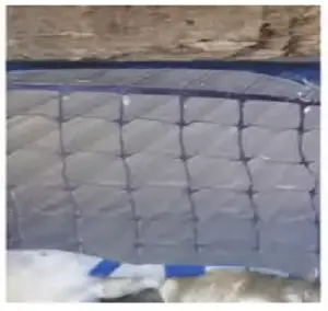
Figures 1 and 2 illustrate the rectangular cavity configurations of the two panels. Their structures resemble open-web trusses with thin horizontal layers and vertical ribs.
Different manufacturers use varying upper and lower surface thicknesses, generally ranging from 0.6 to 0.9 mm. Intermediate layer thicknesses typically range from 0.15 to 0.2 mm.
Finite element deformation patterns satisfy the plane-section assumption, as Figure 3 illustrates. Vertical ribs remain planar and perpendicular to the deformed member axis.
Shear effects and relative sliding between layers can therefore be neglected. The individual layers deform compatibly throughout the cross-section.
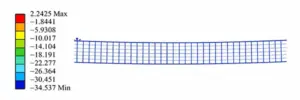
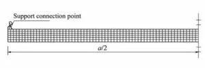
Figure 4 identifies the short-span dimension a, corresponding to the characteristic width in Equation (1). This dimension controls the displacement response under the selected plate theory.
The upper and lower surface layers generally measure three to six times thicker than the intermediate layers. They also lie farthest from the neutral axis.
The vertical ribs run perpendicular to the short-span direction, so their contribution to vertical bending stiffness can be neglected. Figure 5 illustrates the corresponding cross-sectional dimensions.
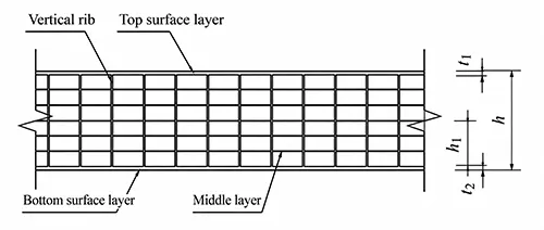
The equivalent thickness calculation can therefore focus on the upper and lower surface layers. Equations (3) and (4) apply to U-shaped hollow panels with different internal cavity configurations.
Here, t1 and t2 represent the upper and lower surface layer thicknesses, respectively. The parameter h denotes overall panel thickness, while h1 represents the centroidal-axis height above the lower surface.
Polycarbonate has a relatively low elastic modulus, approximately one-thirtieth that of glass. Therefore, deformation generally governs the structural performance of U-shaped hollow roofing panels.
Engineering experience indicates that maximum vertical displacement can reach one to five times the equivalent thickness. Equation (1) would substantially overestimate displacement under these conditions.
The influence of large-displacement effects must therefore receive explicit consideration. Ignoring these effects can produce unrealistic theoretical results.
Calculation Based on Theoretical Equation (1)
The theoretical analysis considers 30 mm thick U-shaped hollow panels acting as single-span, one-way plates. Each panel extends approximately 7.73 m along its longitudinal direction.
Secondary purlins support the panels along their long edges. T-shaped supports connect the panels to these purlins at 600 mm intervals.
The material has an elastic modulus of 2,400 MPa and a Poisson’s ratio of 0.40. These properties remain consistent throughout the theoretical calculations.
Panel A contains six layers and five cavities, with a short-span width of 1.05 m. Its upper and lower surface layers each measure 0.6 mm, while intermediate layers measure 0.20 mm.
Panel B contains seven layers and six cavities, with a short-span width of 1.04 m. Its upper and lower layers measure 0.9 and 0.75 mm, respectively, while intermediate layers measure 0.15 mm.
Tables 1 and 2 present theoretical maximum vertical displacements for Panel A under positive and negative pressure. Tables 3 and 4 provide corresponding results for Panel B.
| Parameter | 0.5 | 2.5 | 3.74 | 4.5 | 5.5 |
|---|---|---|---|---|---|
| Positive Pressure (kPa) | 0.5 | 2.5 | 3.74 | 4.5 | 5.5 |
| Maximum Vertical Displacement (mm) | 10.2 | 51.2 | 76.6 | 92.2 | 113 |
Table 1. Theoretical Maximum Vertical Displacement of Panel A Under Positive Pressure
| Parameter | −0.7 | −1.4 | −2.1 |
|---|---|---|---|
| Negative Pressure (kPa) | −0.7 | −1.4 | −2.1 |
| Maximum Vertical Displacement (mm) | −14.3 | −28.7 | −43.0 |
Table 2. Theoretical Maximum Vertical Displacement of Panel A Under Negative Pressure
| Parameter | 0.5 | 2.5 | 3.74 | 4.5 |
|---|---|---|---|---|
| Positive Pressure (kPa) | 0.5 | 2.5 | 3.74 | 4.5 |
| Maximum Vertical Displacement (mm) | 7.2 | 36.1 | 54.1 | 65.1 |
Table 3. Theoretical Maximum Vertical Displacement of Panel B Under Positive Pressure
| Parameter | −0.7 | −1.4 | −2.1 | −3.0 | −3.5 |
|---|---|---|---|---|---|
| Negative Pressure (kPa) | −0.7 | −1.4 | −2.1 | −3.0 | −3.5 |
| Maximum Vertical Displacement (mm) | −10.1 | −20.2 | −30.4 | −43.4 | −50.6 |
Table 4. Theoretical Maximum Vertical Displacement of Panel B Under Negative Pressure
These results show a linear relationship between applied pressure and maximum vertical displacement. Increasing pressure produces a proportional increase in theoretical displacement magnitude.
Experimental Study
Experimental Parameters
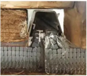
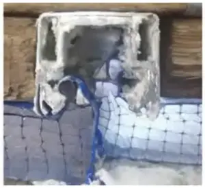
The experimental panels use the same dimensions and material parameters as the theoretical models in the previous section. Figures 6 and 7 illustrate the physical support connections of Panels A and B.
Experimental Procedure
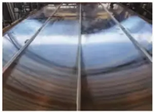
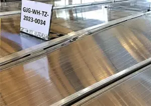
The experiment uses four U-shaped hollow panels together to reduce boundary-condition effects. Figure 8 shows the combined panel arrangement.
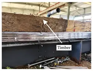
Wooden beams surround the panel assembly, as Figure 9 illustrates. F-clamps secure the wooden beams to create an airtight enclosure and prevent pressurized air leakage.
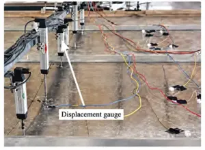
Displacement gauges monitor vertical movement at critical locations during loading. The gauges primarily occupy the midspan regions and support areas of the two central panels.
Figures 10 and 11 illustrate gauge arrangements for positive and negative pressure testing. These measurements provide detailed displacement responses throughout the loading process.
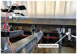
Both tests simulate uniformly distributed wind loads across the complete panel span. Positive and negative wind pressures represent the corresponding loading directions.
The loading procedure uses graded pressure increments and decrements. Each pressure change must not exceed 250 Pa, and the test requires at least four loading stages.
Each pressure stage lasts at least 10 seconds. After each stage, researchers inspect the panels, self-tapping screws, aluminum covers, and T-shaped supports.
They record vertical displacement values and monitor structural damage until failure occurs. The test also documents deformation patterns, failure loads, and failure locations.
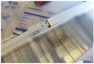
Figures 12 through 15 illustrate the failure conditions of Panels A and B under both pressure directions. Both panels experienced failure of the aluminum locking covers.
The failure caused the U-shaped hollow panels to separate from their aluminum T-shaped supports. This connection failure governed the observed ultimate behavior.


Experimental Results
Tables 5 and 6 present the maximum vertical displacement measurements for Panel A under positive and negative wind pressures. Tables 7 and 8 provide corresponding measurements for Panel B.
| Parameter | 0.5 | 2.5 | 3.74 | 4.5 | 5.5 |
|---|---|---|---|---|---|
| Positive Wind Pressure (kPa) | 0.5 | 2.5 | 3.74 | 4.5 | 5.5 |
| Maximum Vertical Displacement (mm) | 3.9 | 25.6 | 36.0 | 41.6 | 49.4 |
Table 5. Experimental Maximum Vertical Displacement of Panel A Under Positive Wind Pressure
| Parameter | −0.7 | −1.4 | −2.1 |
|---|---|---|---|
| Negative Wind Pressure (kPa) | −0.7 | −1.4 | −2.1 |
| Maximum Vertical Displacement (mm) | 16.6 | 32.1 | 41.3 |
Table 6. Experimental Maximum Vertical Displacement of Panel A Under Negative Wind Pressure
| Parameter | 0.5 | 2.5 | 3.74 | 4.5 |
|---|---|---|---|---|
| Positive Wind Pressure (kPa) | 0.5 | 2.5 | 3.74 | 4.5 |
| Maximum Vertical Displacement (mm) | 10.0 | 31.0 | 40.0 | 46.2 |
Table 7. Experimental Maximum Vertical Displacement of Panel B Under Positive Wind Pressure
| Parameter | −0.7 | −1.4 | −2.1 | −3.0 | −3.5 |
|---|---|---|---|---|---|
| Negative Wind Pressure (kPa) | −0.7 | −1.4 | −2.1 | −3.0 | −3.5 |
| Maximum Vertical Displacement (mm) | 15.9 | 27.6 | 36.6 | 41.4 | 39.2 |
Table 8. Experimental Maximum Vertical Displacement of Panel B Under Negative Wind Pressure
The experimental results reveal a nonlinear positive relationship between pressure magnitude and maximum vertical displacement. Displacement generally increases with loading, but its growth rate gradually decreases.
To be continued…